I just released an updated version of the Maker Project Canvas (v2). It’s a one-page visual tool for planning, organizing, and communicating your projects. Here are some resources:
Download the Concept and Full canvas PDF files from Github.
Download the Maker Project Canvas Workbook from here.
Adafruit has put 8 WS2812 RGB LEDs on a PCB, calling it a NeoPixel Stick. It is a very convenient way to experiment with these LEDs since an Arduino library has been written taking the heavy lifting out of the serial interface.
While RGB LEDs are very cool, simply looking at them head on is not the best way to use them- they are pretty bright and there are more artful ways to apply them. One approach is to use them as the illumination source in backlighting optics. Backlighting optics are typically used behind LCD displays to provide a uniform illumination across the display from white LEDs edge-lighting a diffusing plate. The light travels inside the panel, trapped by total internal reflection, until it encounters a scattering mechanism that directs it out of the surface of the plate.
The following details a quick prototype using two NeoPixel Sticks.
Backlight Panel
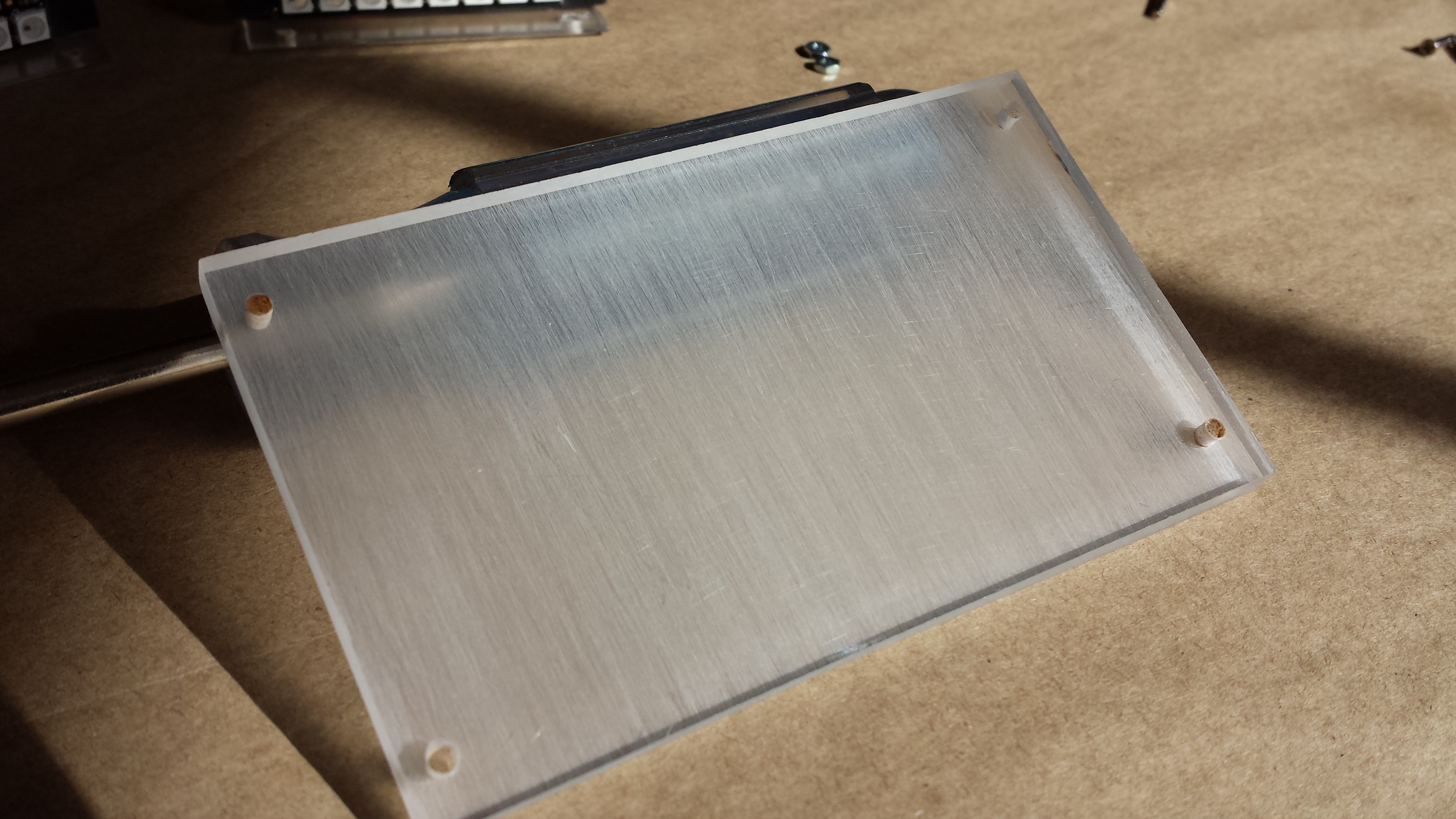
A really crude optical diffusing plate was created from a 2.5″ x 5.5″ piece of 0.220″ clear acrylic. NeoPixel Sticks are 2″ long, so this width provided an area for mounting screws. Backlight panels use several methods to redirect the edge-launched light out of the plane of the panel. The method used here was to engrave lines into the back surface parallel to the edges with the LED strips. The “engraving” method was quite crude: various grades of sandpaper were used to place scratches parallel to the LED strips. A well-designed backlight attempts to vary the engraving pattern to take into account how the intensity of the light falls off from the source. This prototype may be well-intentioned, but it is not particularly well-designed. The center of the panel was sanded with 80-grit sandpaper while the areas nearer the LED strips were sanded with 60-grit and the areas adjacent to the LED strips used 150-grit sandpaper.
Crude Backlight Panel
Backlights usually use a diffuser sheet above the panel. A piece of frosted plastic cut from a stencil sheet was used. A piece of 3″ x 5″ card was also used beneath the panel to scatter light that leaked out the back face.
Assembly
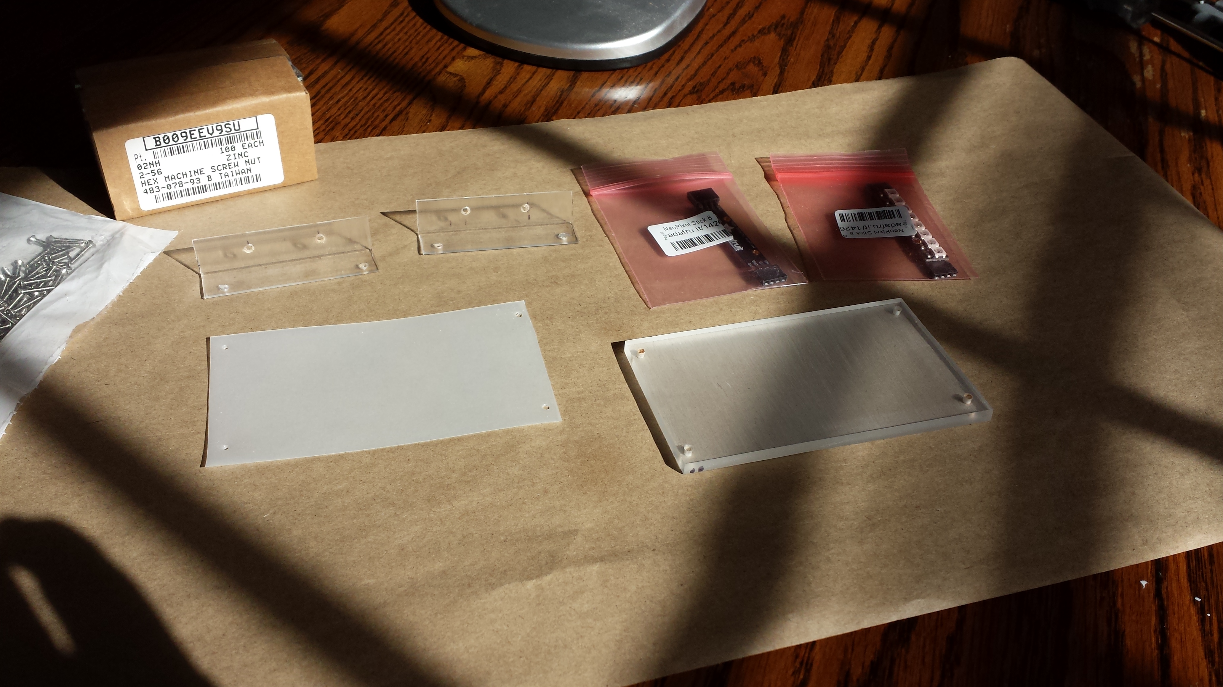
The NeoPixel Sticks were mounted on 0.5″ plastic L-brackets cut and drilled to size. The components are shown below:
Backlight Prototype Components
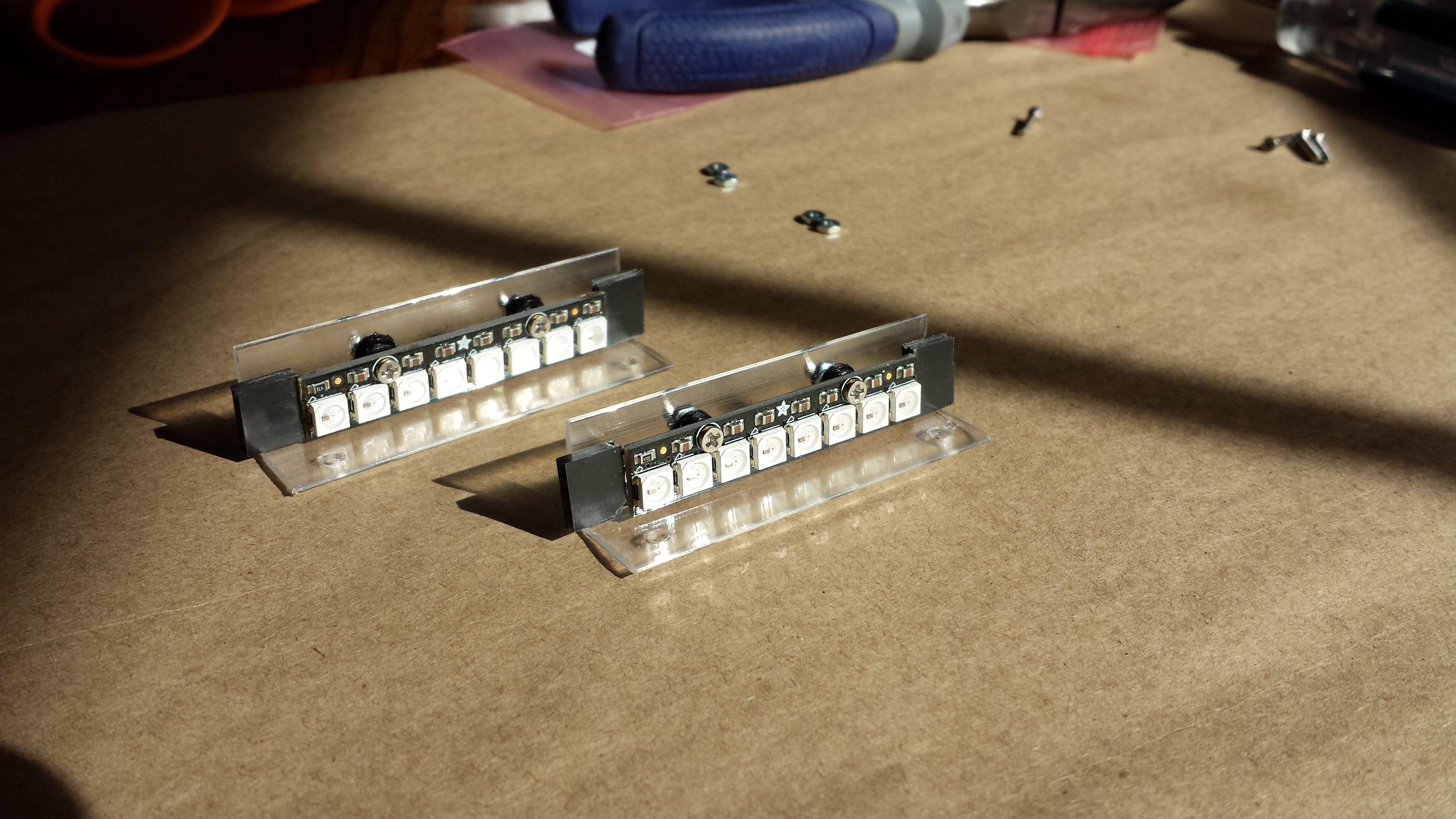
Four-pin headers were soldered to the NeoPixel Sticks to make it easy to use pre-made jumper cables to connect to an Arduino Uno. A couple of nylon washers were used on each 2-56 screw to provide a standoff creating clearance for the headers.
NeoPixel Sticks Mounted to L-brackets
Here is a back view of the assembled panel (note: the light is from an external lamp, not the NeoPixels):
Backview of Assembly
Here is the front view of the assembled panel (again with an external lamp lighting it):
Front view of Assembled Backlight
Arduino Connections
Pin 6 on the Arduino was used to provide DataIn to the first NeoPixel Stick. Ground and +5V were provided with jumpers from the Arduino headers. Jumpers were used to connect DataOut from the first NeoPixel Stick to the DataIn of the second stick, along with power and ground.
Backlight Connected to an Arduino Uno
The Adafruit NeoPixel Library provides a demonstration sketch (strandtest.ino) that was used without modification to drive the backlight to see if it worked, which it did. The code was then modified to explore several color effects and look at illumination intensity.
Backlight Test
Here are two examples of full intensity with all LEDs turned on. First in a white mode with RGB = (255,255,255):
White Mode
Here is green mode with RGB = (0,255,0):
Green Mode
In operation, the LED strips will be hidden. The above show that the uniformity could use improvement. However, the results were rather pleasing!
Flipboard is a nice news reader that collects interesting articles across the web and presents them in magazine style. You can even create your own magazines and share them. I did just that for Internet of Things articles: iot: “Internet of Thingd”.
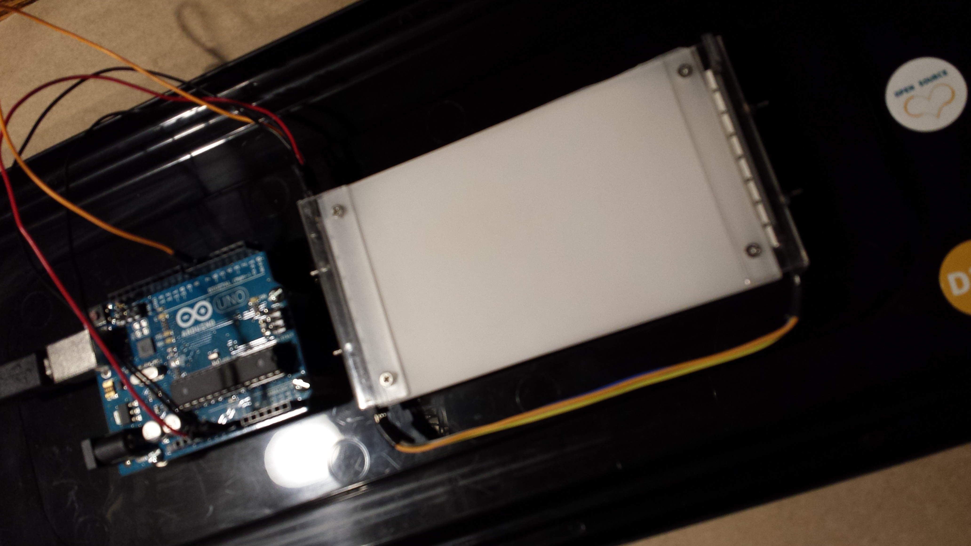
The Arduino CapacitiveSensor library by Paul Stoffregen/Paul Badger provides a nice way to add touch sensing to projects. Unfortunately, there doesn’t seem to be a port to the Spark Core platform. This fact and the desire to better understand how the original library worked, lead to some effort to develop touch sensing on the Spark Core.
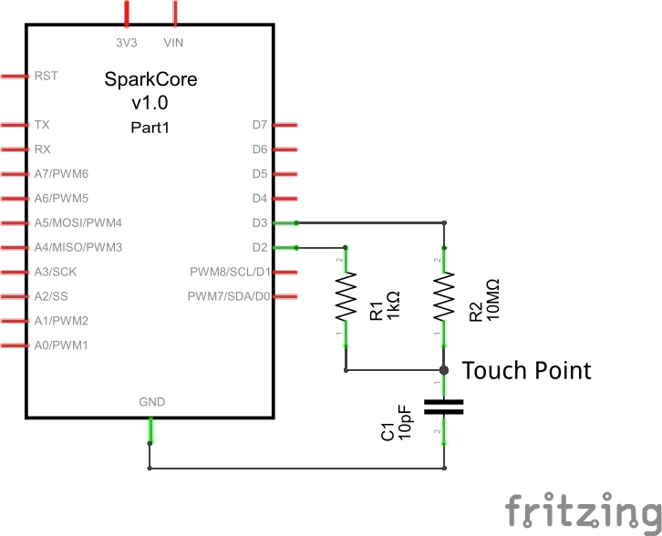
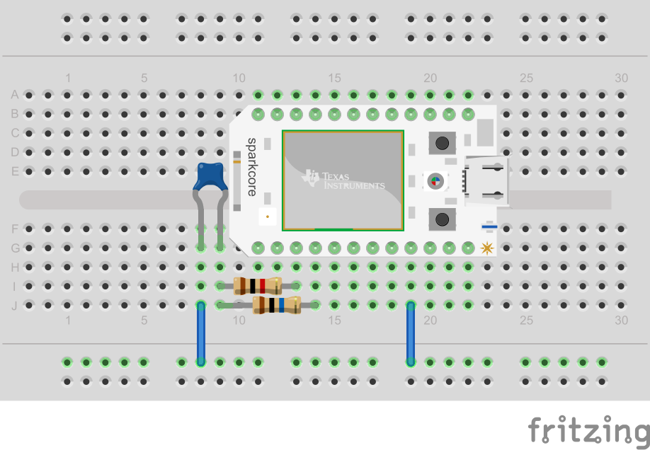
The capacitive sensing technique sends a LOW to HIGH transition from pin D3 through a large value resistor (~10Mohm) to sensing pin D2, as shown in the schematic below. A 1kohm series resistor was put in series with D2 and the connection to the 10Mohm resistor to increase protection against ESD. Stray or intentional capacitance (10pF shown in the schematic) forms an RC low-pass that slows down the rising edge of the transition. This causes a time delay for the signal at D2 to reach the voltage threshold to be detected as a HIGH, as shown in the timing diagram.
When the node connecting the resistors is touched, additional capacitive loading is introduced which further delays the arrival of the pulse. By comparing the arrival time against the baseline (untouched) arrival time, touching of the node can be detected. A baseline calibration is maintained by an exponential moving average of readings below the threshold of excessive delay (< 1.25 * Tbaseline). This accommodates slow drifts due to temperature or humidity changes.
Because capacitance will hold charge (and the impedance is high), it needs to be discharged prior to each reading of arrival time. This is accomplished by setting pin D2 to an output in a LOW state and then setting it back to a high impedance input. The code takes 32 readings and averages them to help filter noise. The Spark micros() function is used, along with attaching an interrupt to the sensing pin D2 to note when the threshold voltage was achieved. Micros() will periodically roll-over due to long data type limits, so these (infrequent) data points are ignored in the average calculation.
In further post-processing, the readings are debounced like a mechanical switch, in a function that reports ‘Touch Events’: tEVENT_NONE, tEVENT_TOUCH, tEVENT_RELEASE.
The Loop() then periodically polls for Touch Events (every POLL_TIME milliseconds). The Spark Core on-board LED D7 is lit when a tEVENT_TOUCH occurs and turned off when a tEVENT_RELEASE is sensed.
The Arduino version uses a pseudo-differential sensing technique to help reduce noise: readings are taken for both a LOW to HIGH and HIGH to LOW transition and then averaged. This could be incorporated.
Additional, this technique can get encapsulated in a library.